![]()
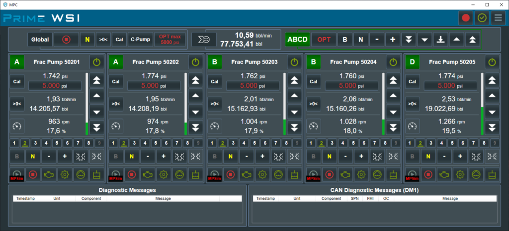
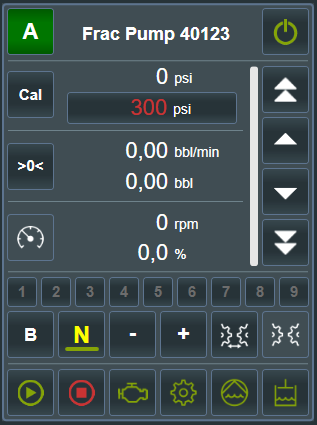
![]() Switch Over Control – activate pump control from MPC software
Switch Over Control – activate pump control from MPC software
![]() Assign To Group – allow to control from group control bar
Assign To Group – allow to control from group control bar
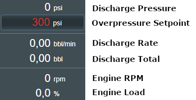
![]() Overpressure Setpoint – display and set overpressure setpoint
Overpressure Setpoint – display and set overpressure setpoint
![]() Calibrate Pressure Sensor Range – short click calibrates offset, long click offset and gain
Calibrate Pressure Sensor Range – short click calibrates offset, long click offset and gain
![]() Reset Total – reset discharge total valu to ‘0’
Reset Total – reset discharge total valu to ‘0’
![]()
![]()
![]()
![]() Engine Throttle Up/Down – speed up or down engine
Engine Throttle Up/Down – speed up or down engine
![]()
![]() Set Gear – increase or decrease gear
Set Gear – increase or decrease gear
![]() Set Gear – switch to selected gear 1-9
Set Gear – switch to selected gear 1-9
![]() Brake – activate internal transmission brake or external brake
Brake – activate internal transmission brake or external brake
![]() Switch to Instant Neutral – switch transmission to neutral and set throttle to ‘0’
Switch to Instant Neutral – switch transmission to neutral and set throttle to ‘0’
![]()
![]() Transmission Lockup Inhibit – activate lockup inhibit (blinking when activated)
Transmission Lockup Inhibit – activate lockup inhibit (blinking when activated)
![]() Lockup Indicator – displays current transmission lockup state
Lockup Indicator – displays current transmission lockup state
![]()
![]() Start/Stop Engine – click or click and hold to start/stop engine
Start/Stop Engine – click or click and hold to start/stop engine
![]()
![]()
![]()
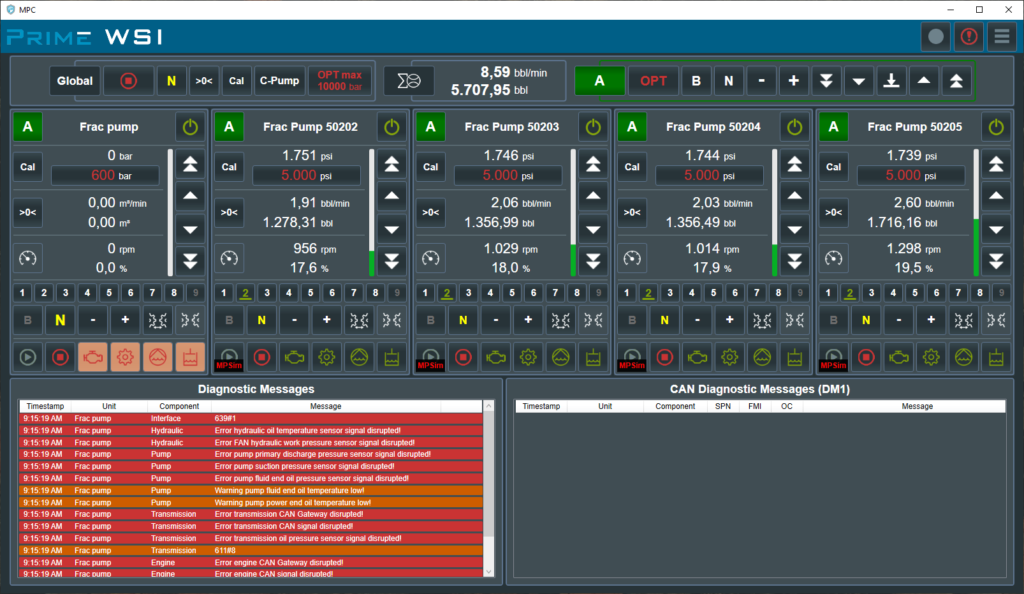
![]() Show Details – open a window with monitored parameters / error indicators
Show Details – open a window with monitored parameters / error indicators

![]() Stop engine – stop all engines
Stop engine – stop all engines
![]() Switch to Instant Neutral – switch all transmissions to Instant Neutral
Switch to Instant Neutral – switch all transmissions to Instant Neutral
![]() Calibrate Pressure Sensor Range – calibrate all pressure sensors
Calibrate Pressure Sensor Range – calibrate all pressure sensors
![]() Reset Total – reset all discharge totals
Reset Total – reset all discharge totals
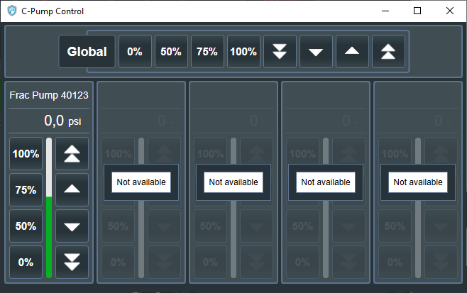
![]() C-Pump – Open C-Pump Control Window
C-Pump – Open C-Pump Control Window
![]() Overpressure Setpoint Limit – Set Global Overpressure Setpoint Limit
Overpressure Setpoint Limit – Set Global Overpressure Setpoint Limit

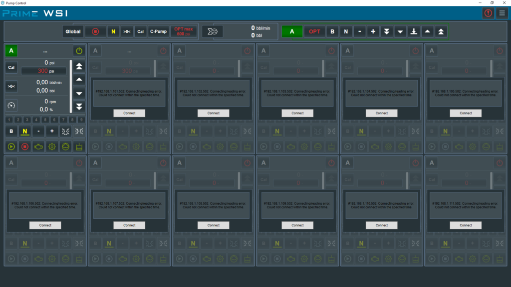
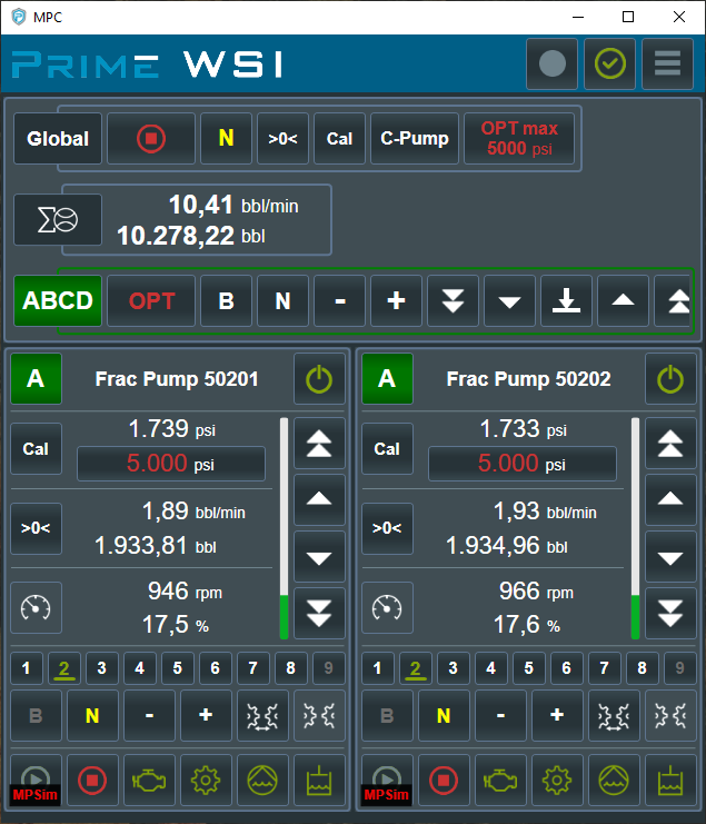
![]() Selected Group – selected Pump group to control
Selected Group – selected Pump group to control
![]() Ovepressure Setpoint – set overpressure setpoint in all pumps in group
Ovepressure Setpoint – set overpressure setpoint in all pumps in group
![]()
![]()
![]()
![]() Transmission Control – Brake, Neutral, Set Gear
Transmission Control – Brake, Neutral, Set Gear
![]()
![]()
![]()
![]() Engine Throttle Up/Down – speed up or down engine
Engine Throttle Up/Down – speed up or down engine
![]() Sync RPM – set all engine RPM in group to the smallest engine RPM in the group
Sync RPM – set all engine RPM in group to the smallest engine RPM in the group


![]()
![]()
![]()
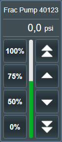
![]() C-Pump Speed – Set C-Pump speed to 0, 50, 75 or 100%
C-Pump Speed – Set C-Pump speed to 0, 50, 75 or 100%
![]()
![]()
![]()
![]() C-Pump Speed Up/Down – Increase/Decrease C-Pump speed
C-Pump Speed Up/Down – Increase/Decrease C-Pump speed
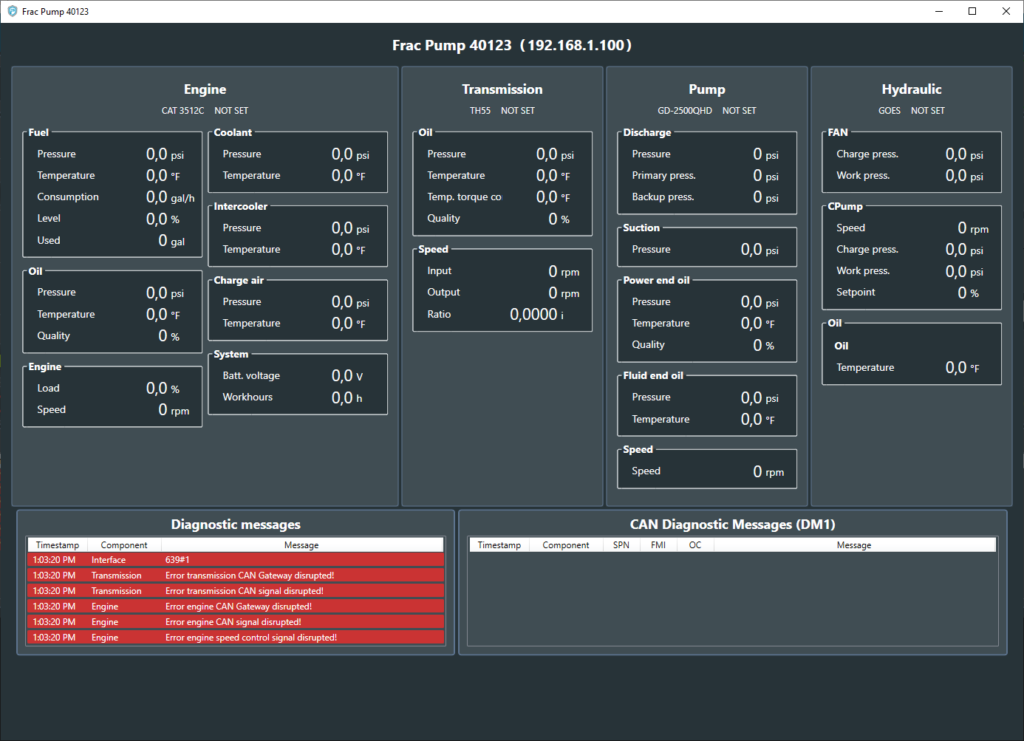
To open Details Window click on one of the following buttons:
![]()
![]() Engine
Engine
![]()
![]() Transmission
Transmission
![]()
![]() HP Pump
HP Pump
![]()
![]() Hydraulic system
Hydraulic system
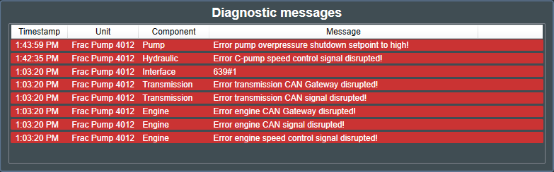
Red symbols and blinking indicates that one or more errors occured.
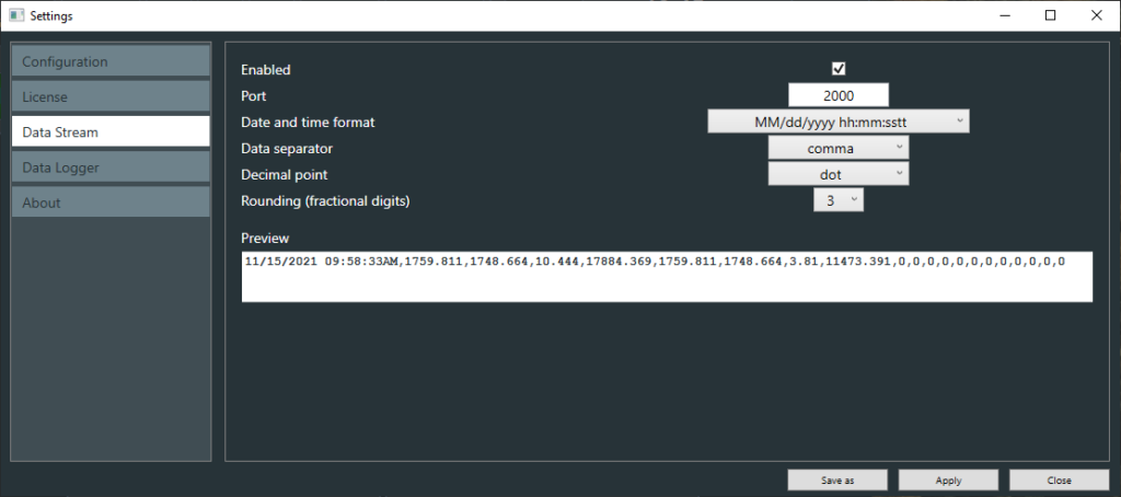
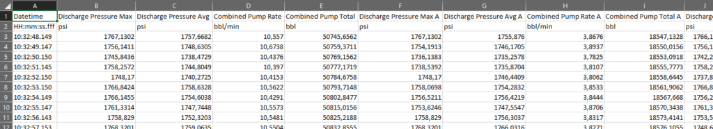
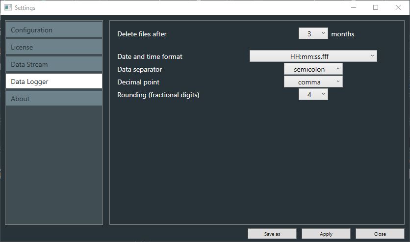
MPC Data Logger allows to log data in CSV file. To start logging data to file click on Data Logger ![]() on top right side on main screen.
on top right side on main screen.
Logging data is indicated by blinking red circle ![]()
By selected option ‘Autostart’ data logging starts automatically with program start.
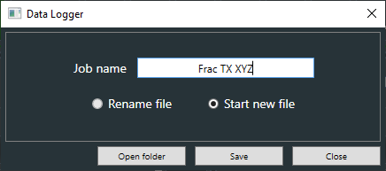
In job name window user can assign a name of existing data file or start new file.
All data files are stored in default MPC folder. To navigate to that folder use ‘Open folder’ button.
Data filenames are combined from timestamp and job name:
![]()
When job name is empty filename contains only timestamp. The filename can be renamed every time even during logging to file.
Logging is possible only when minimum one pump is connected.
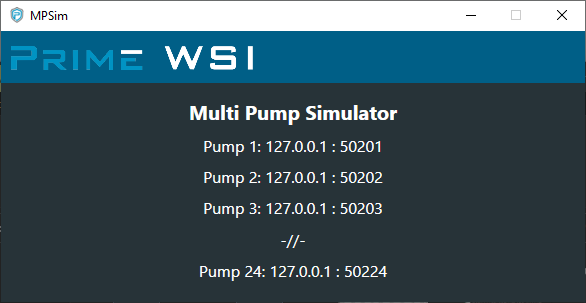
MPSim is a Multi Pump Simulator software that allows user test almost all MPC features. MPSim is a part of MPC installation and will be installed together with MPC.
To start MPSim click on icon